15-25KV Shielded MV-105 cable Application
15-25KV Shielded MV-105 cable is primarily used for power circuits in commercial, industrial, refinery and petro-chemical plants; utility power generation and substations. The cable can be installed in wet or dry applications and is for use in aerial, conduit, open tray, and underground duct installations. It can be used in direct burial if installed with a ground conductor in close proximity. The cable is approved for temperature up to 105°C and voltages up to 25kV.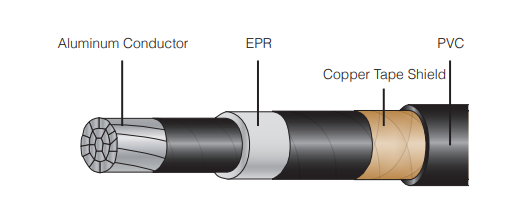
15-25KV Shielded MV-105 Cable Specifications
CONDUCTORS: Stranded 1350 series aluminum, compact Class B stranding per ASTMCONDUCTOR SHIELD: Extruded thermoset semi-conducting stress-control layer over conductor
INSULATION: High dielectric strength EPR insulation with or without lead, contrasting in color to the black semi-conducting shield layers, extruded over the conductor shield
INSULATION SHIELD: Extruded, strippable semi-conducting layer over the insulation
METALLIC SHIELD: Helically applied 5 mil annealed copper tape over the insulation shield with an overlap of 25%
JACKET: Black low-friction, lead-free, flame-retardant, moisture and sunlight resistant polyvinyl chloride (PVC) jacket tightly applied over the copper tape
Optional water block available upon request
15-25KV Shielded MV-105 Cable Standards
Meets or exceeds the following standards as applicable:• UL 1072
• UL Listed as Type MV-105 for use in accordance with NEC
• AEIC CS8
• ICEA S-93-639/NEMA WC74
• ICEA S-97-682
• IEEE 1202 Flame Test (70,000 BTU/hr)/CSA FT4
• EPA 40 CFR, Part 261 for leachable lead content per TCLP method
• ASTM B230, B400
• Sunlight Resistant, listed and marked
• NFPA 70 NEC
• OSHA Acceptable
• UL 1685 (Sizes 1/0 AWG and larger) UL Flame Exposure Test
• Sizes 1/0 AWG and larger are listed and marked “FOR CT USE”
• Temperature Rating: 105°C Continuous, 140°C Emergency Overload, 250°C Short Circuit
Aluminum Conductor EPR/PVC Copper Tape Shield Cable Specification Data
| Size AWG |
Conductor Diameter | 0220”(5.59mm) Insulation Diameter |
Extruded Shield |
Insulation iameter |
Min. Jacket |
Point hickness |
Approx.Overall Diameter |
Approx Net Weight |
Allowable Ampacities | ||||
| inch |
mm |
inch |
mm |
inches |
mm |
inch |
mm |
inch |
mm |
Ibs/mft |
Duct |
Conduit in Air |
|
| 2 | .268 | 6.80 | .759 | 19.27 | .815 | 20.70 | 0.07 | 1.78 | .982 | 24.94 | 488 | 130 | 130 |
| 1 | .299 | 7.59 | .789 | 20.04 | .845 | 21.46 | 0.07 | 1.78 | 1.012 | 25.70 | 523 | 145 | 150 |
| 1/00 | .336 | 8.53 | .826 | 20.98 | .882 | 22.40 | 0.07 | 1.78 | 1.049 | 26.64 | 575 | 165 | 170 |
| 2/00 | .376 | 9.55 | .866 | 21.99 | .922 | 23.41 | 0.07 | 1.78 | 1.089 | 27.66 | 627 | 190 | 200 |
| 3/00 | .423 | 10.74 | .911 | 23.15 | .967 | 24.56 | 0.07 | 1.78 | 1.134 | 28.80 | 690 | 215 | 225 |
| 4/00 | .475 | 12.06 | .959 | 24.35 | 1.017 | 25.83 | 0.07 | 1.78 | 1.184 | 30.07 | 758 | 245 | 260 |
| 250 | .520 | 13.20 | 1.017 | 25.83 | 1.075 | 27.30 | 0.07 | 1.78 | 1.242 | 31.54 | 837 | 270 | 290 |
| 350 | .616 | 15.65 | 1.094 | 27.78 | 1.170 | 29.71 | 0.07 | 1.78 | 1.337 | 33.96 | 994 | 330 | 350 |
| 500 | .736 | 18.69 | 1.21 | 30.8 | 1.29 | 32.76 | 0.07 | 1.78 | 1.457 | 37.0 | 1217 | 400 | 430 |
| 750 | .908 | 23.06 | 1.396 | 35.45 | 1.47 | 37.33 | 0.07 | 1.78 | 1.639 | 41.6 | 1583 | 490 | 540 |
| 1000 | 1.06 | 26.92 | 1.546 | 39.26 | 1.62 | 41.21 | 0.07 | 2.54 | 1.852 | 47.0 | 2026 | 565 | 640 |